What is Soil Resistivity Testing?
The ability of a grounding system to conduct a fault current into the soil is directly dependent on the resistivity of the soil. Knowing the soil resistivity is the first and most important step in an accurate calculation of the ground resistance. The same grounding system which is ideal in one type of soil for a certain fault condition may become dangerous in a second type of soil or over-designed in a third type of soil. It all depends on the soil resistivity at each location.
In power system engineering applications, the soil resistivity testing is used almost exclusively to determine the best location and depth for a low resistance electrode or grounding system.
The soil resistivity testing may be used in other domains as well. For example, it can indicate the degree of corrosion to be expected in underground metallic pipes. In geophysical prospecting, it is used to locate ore bodies, depth of bedrock, etc…
Wenner Resistivity Method
The most common method for soil resistivity testing is the Wenner method. This method, when used with suitable test equipment, will provide sufficient data for an accurate earth structure model. Because of the relative simplicity of results interpretation and widespread availability of test equipment supporting the use of this method, it is recommended as a standard test procedure.
Dr. Frank Wenner of the U.S. Bureau of Standards developed the theory behind this test in 1915.

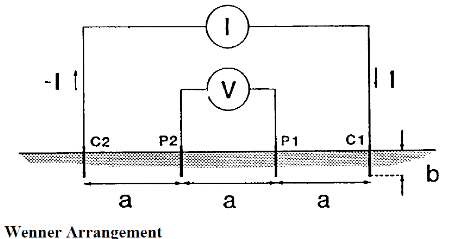
The Wenner four-electrode arrangement is shown above. Four electrodes are driven into the earth along a straight line. The electrodes are uniformly spaced, and the burial depth of the electrodes is less than 10% of the spacing between two adjacent electrodes. Therefore, each electrode will appear as a point with respect to the distances involved in the measurement. A current I is injected into the earth via two outer electrodes and the earth’s surface potential difference V is measured by the two inner electrodes. The outer electrodes are called the current electrodes and the inner pair, potential electrodes. The ratio V/I with the dimension of resistance is proportional to a variable described as the apparent resistivity ρa at spacing a. The proportionality factor between V/I and ρa is called the array geometric factor α. Thus, the following equation can be written:

In most cases, the soil structure is not uniform. The subsurface structure of the Earth consists of multiple layers of various resistivities. Because of this variation of soil resistivity with depth, it is essential to have the testing described above performed at various spacings (a). This will translate into information about apparent resistivity (ρa) at various depths. Using this information, the actual earth structure at the location of the future grounding system can be modeled as an equivalent multi-layer soil structure.
A grounding calculation based on a multi-layer earth model will always be more precise than an approach based on uniform soil. For this reason, a valid soil resistivity test is an essential component of a good grounding system design and it has a fundamental importance in the accurate prediction of a grounding system performance during line-to-ground faults or lightning conditions. Read more about our grounding products and implementation services today!